ACCELERATOR, RAY AND APPLICATIONS
Research on the absolute measurement of air kerma in superficial X-ray radiotherapy
Nuclear Science and Techniques|Vol. 37, No. 8|Article ID: 138|Print 2026-08|Online 2026-05-19
DOI: 10.1007/s41365-026-01953-yCSTR: 32136.14.NST.2026.08138
Scar formation results from nonregenerative healing after tissue injury. Complications may occur if the scar grows beyond a certain threshold. Superficial X-ray radiotherapy offers significant advantages as an adjuvant method for surgical treatment of scars. Following the widespread application of the superficial X-ray radiotherapy system SRT-100, accurate dose measurements are key to the implementation of superficial X-ray radiotherapy. In this study, the absorbed dose measured in superficial X-ray radiotherapy was traced to the primary standard based on air kerma. According to this principle, based on the technical parameters of the SRT-100 system, this study establishes the corresponding reference radiation qualities by relying on an industrial X-ray tube and uses a free-air ionization chamber to obtain the corresponding correction factors through experiments and simulations to realize absolute air kerma measurements and uncertainty evaluations. In this context, air kerma calibration and associated uncertainty evaluations were performed for the parallel-plate transfer ionization chambers PTW23342 and PTW23344. The results show that the mean energies of the fluence spectra simulated at the X-ray tube voltages of 50, 70, and 100 kV were 26.2, 34.1, and 44.7 keV, respectively. The measured results of the first half-value layer at the three tube voltages were 0.538, 1.146, and 2.190 mmAl. The air kerma of three radiation qualities were 1.487, 1.436, and 1.268 mGy/s. The expanded measurement uncertainty of air kerma by the free-air ionization chamber was 0.94% (k = 2), and the expanded uncertainties of the calibration factor in the two transfer ionization chambers were 1.00% (k=2) and 0.96% (k=2).
Introduction
Scars are the result of abnormal repair after skin injury; they affect the appearance of the skin and the mental health of patients [1]. Following rapid economic developments, an increasing number of patients with scars have undergone treatments for abnormal scars. Surgical resection is a traditional, direct, and effective abnormal scar treatment. However, there are potential dangers after scar resection surgery, such as the formation of new scars, pigmentation, and skin asymmetry [2-4]. After years of clinical practice, clinicians have recognized the efficacy of resection combined with radiotherapy as the preferred treatment for recurrent scars [5-9]. The radiotherapy methods for scars include electron-beam therapy, superficial X-ray therapy, and brachytherapy [10]. The advantages of superficial X-ray radiotherapy over other radiotherapy modalities include a lower radiation energy and a more superficial dose to the skin. This is because the transient high-dose area is mainly concentrated on the skin surface, with minor effects on deeper tissues and organs; furthermore, the requirements for radiation protection are relatively simple [11]. Superficial X-ray therapy is extensively used in postoperative radiotherapy for scars because of its simple operation, low cost, and capacity to achieve significant postoperative recovery [12, 13]. Several domestic institutions have introduced superficial X-ray radiotherapy systems. However, inappropriate doses can lead to unsatisfactory therapeutic effects [14]. Research has shown that the total radiation dose of radiotherapy should range from 15 to 20 Gy to maintain a low-incidence scarring rate without affecting the efficacy of radiotherapy [15, 16].
A prerequisite for effective radiotherapy is the accurate measurement of the absorbed dose in normal and diseased tissues. The detectors and measurement methods usually refer to the TG 61 of the American Association of Physicists in Medicine, the Institute of Physics and Engineering in Medicine and Biology code in the United Kingdom, and the TRS 398 of the International Atomic Energy Agency [17-19]. These reports indicate that the absorbed dose of low-energy X-rays can be traced to the air kerma. The parallel-plate ionization chamber and the corresponding phantom were used to measure the absorbed dose to water using the ionization method, and relevant conversion factors were multiplied to obtain the traceability of the absorbed dose to water [20]. To ensure the accuracy of the measured dose based on the technical parameters of the X-ray radiotherapy system SRT-100, an industrial X-ray tube was used to establish the X-ray reference radiation qualities. A free-air ionization chamber (FAC) was used to complete the absolute measurement of air kerma under the corresponding radiation qualities. Parallel-plate transfer ionization chambers were calibrated, and the results were compared with international comparison results to verify the accuracy of the absolute air kerma measurements in superficial X-ray radiotherapy.
Experimental principles and methods
X-ray radiation device
X-ray radiation devices consist of an X-ray system, a beam-limiting diaphragm, an additional filtration system, guide rails, a positioning system, and a microcurrent measurement system [21]. The X-ray tube model was MG165 equipped with a tungsten target, and the target angle was 20°. Inherent filtration was achieved with the use of beryllium (thickness of 0.8 mm). A high-voltage generator with a tube voltage of 7.5 160 was used. Different reference radiation qualities can be established by adjusting the tube voltage and enhancing filtration by using a filter element with an increased thickness. A beam-limiting diaphragm was used to confine and collimate X-rays. It had an inner diameter of 7 mm, an outer diameter of 6 cm, and a thickness of 4 mm. The material was composed of 93% pure tungsten and 7% pure Ni–Fe. A uniform radiation field was formed at the reference plane to satisfy the measurement and calibration requirements of the air kerma. The principle of the microcurrent measurement system is based on the high-gain negative feedback method; this system consists of an external capacitor, a Keithley electrometer (model 6517), a thermometer, a barometer, and the LabVIEW software program, which is used to achieve automatic control and acquisition functions. The microcurrent measurement system can measure the ionization charge with temperature and pressure corrections in real time.
FAC
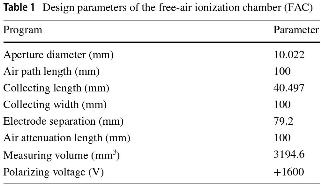
The FAC can measure X-rays in the range of 8–100 kV. It serves as the core of the low-energy primary standard of air kerma and can achieve absolute air kerma measurements [22]. The design parameters of the FAC are listed in Table 1. The National Institute of Metrology in China used the FAC in a 2018 international key comparison effort and realized international equivalence [23]. The parallel X-ray beam generated by the X-ray tube enters the FAC through the front diaphragm such that the central axis of the X-ray beam is parallel and equidistant from the upper and lower electrodes. The X-ray beam leaves the FAC through the back hole. The ionization chamber was designed to measure the photon energy in the range of 8–100 keV. The design parameters of FAC are listed in Table 1.
Design parameters of the free-air ionization chamber (FAC)
Monte Carlo simulation software
A Monte Carlo simulation software program is typically used to simulate parameters that cannot be obtained directly or are difficult to obtain in the experiment; these parameters are used as a guide and constitute the basis for actual measurements. These include correction factors for electron loss, fluorescence scattering, and diaphragm transmission. In this study, a Monte Carlo simulation was used to obtain the correction factors. The electron gamma shower (EGSnrc) software program, developed by the National Research Council Canada, is typically used for Monte Carlo simulations in radiation dosimetry. Kawrakow [24] quantitatively analyzed the problems associated with EGS4, which made it difficult to simulate accurately the response of the ionization chamber, and proved that EGSnrc addressed these problems and improved the accuracy of the charged particle transport and atomic scattering cross-section. Fu et al. [25] conducted cone-beam computer tomography simulation research based on the EGSnrc software program and verified the accuracy of the developed system. The spectral results obtained using this program showed good consistency with those obtained from the Spektr software program (a computational tool for X-ray spectrum modeling and analysis); the maximum difference was 3.0%, and the mean difference was lower than 2.0%. The DOSXYZnrc program was used to construct the FAC model. Combined with the egs-view visualization program, associated parameters were set, such as the cavity area, exit particle type and angle, medium, and density correction file. The BEAMnrc software program was used to simulate the fluence spectra of X-ray radiation. By selecting the appropriate simulation particle number, density correction file, incident particle source type and energy, cutoff energy of photons and electrons, interaction between particles, and variance reduction technology, a phase space file with the suffix phsp was obtained. The BEAMdp software program was used in combination with the BEAMnrc program, and the generated phase space file was opened in BEAMdp. According to the maximum and minimum energies of the particle source, the corresponding fluence spectral data were generated, including the number of particles and the uncertainty of different energies, and used to realize the calculation and data visualization of the X-ray fluence spectrum. The C++ application egs-fac implemented the transport of the particles in the FAC and calculated the associated correction factors in a self-consistent manner. The correction factors for electron loss, photon scatter, and fluorescence of low-energy and medium-energy free-air chambers were calculated by Burns [26] using the EGSnrc software program. The results were compared with those of the EGS4 software program and the PENELOPE code. Simultaneously, an uncertainty analysis was conducted, providing new values for the correction factors of the Bureau International des Poids et Mesures (BIPM) standards. This software program simulates and calculates the correction factors under the conditions of no vacuum tube, vacuum tube, and air. An FAC ionization chamber was used in this study. Therefore, correction factors without a vacuum tube were selected, namely diaphragm edge penetration, electron loss, scattering, and fluorescence photon correction factors.
Absolute air kerma X-ray measurements
The FAC operates as follows. Continuous X-rays are produced by the X-ray tube after the electron hits the target and enters the FAC through an enhanced filter and a beam-limiting diaphragm. Positive and negative ions are produced by the interaction between the X-rays and air in the cavity; these ions then move to the collecting plate under the effect of the electric field applied between the electrode plates. The resulting ionization current was measured using a microcurrent-measurement system. The air pressure and temperature in the surrounding area must be immediately monitored and corrected for the ionization current measured by the FAC. The air kerma rate was measured using an FAC according to its definition. The modified equation for the air density is given by Equation (1). (1)where ρ0 is the air density at 273.15 K and 101.325 kPa, and Ta and Pa are the air temperature and pressure during the measurements, respectively.
The air kerma rate was measured by an FAC according to its definition, and the value [27, 28] was calculated using Eq. (2). (2)where V is the effective measurement volume of the FAC, I is the ionization current measured by the chamber, and
 is the mean energy that produces a pair of positive and negative ions in the air. Moreover, g is the fraction of charged particles lost in the air owing to Bremsstrahlung radiation, and
 is the product of the correction factors. The physical constants used for the absolute measurement of air kerma rate in the X-rays are listed in Table 2.
FAC design parameters

Several correction factors affect the design and operation of FAC. These factors were obtained from experimental measurements, Monte Carlo simulations, and recommendations. The correction factors obtained from the experimental measurements are the following: air attenuation correction factor ka, ion recombination loss correction factor ks, wall transmission correction factor kp, polarity correction factor kpol, and electric field distortion correction factor kd. Monte Carlo simulations provide correction factors such as the diaphragm transmission correction factor kdia, the product of the scattering correction factor and fluorescence correction factor  , and the electron loss correction factor ke. Additionally, the product of the initial ion correction factor, the ionization work correction factor
 , and the humidity correction factor kh are from the recommendations.
Air attenuation correction factor In the absolute air kerma measurements, the ionization charge was collected in the collection plate of the FAC. The actual measurement position was the geometric center of the front diaphragm hole in the FAC. An air gap exists between the collection plate and the diaphragm of the FAC, where the X-ray energy is attenuated. Several methods are used to obtain the air attenuation correction factor ka using the vacuum, moving distance, and Monte Carlo methods. In this study, the moving distance method was used to obtain ka [29]. Equations (3) and (4) were used for calculating ka. (3)
 (4)where
 denotes the mass attenuation coefficient, d is an attenuation length of 10 cm, ρ20°C is the air density at the temperature 20 ℃, and I1 and I2 are the ionization currents measured before and after the attenuation through the air distance, respectively.
Ion recombination loss correction factor To eliminate the inaccuracy of the experimental results caused by ion recombination during the measurement process, which yields a smaller measured ionization current than the true value, an ion recombination loss correction factor ks is introduced. Ion recombination includes initial and volume recombinations [30]. In this study, the method recommended by BIPM was used to measure ks [31], implemented by measuring the ionization currents at different tube voltages and currents. Equations (5) and (6) were used for calculations. (5)
 (6)where kinit is the value of the initial recombination, kvol is the volume recombination value, and n is the ratio of the polarizing voltage of +1600 V to the tube voltage of the ionization chamber in the area of the plateau with values of 2.5, 3, and 4 for the tube voltages of +640, +533, and +400 V, respectively. Additionally, a0 is the intercept of the linear fitting equation, and a1 is the slope of the fitting equation. Thus, ks can be expressed by Equation (7).
 (7)where Iv is the ionization current at +1600 V.
Wall-transmission correction factor Some high-energy X-rays enter the ionization chamber from the non-diaphragm hole, resulting in a higher current [32]. To correct the measurements, a wall transmission correction factor kp must be introduced. The incident diaphragm hole of the FAC was sealed with a lead plug to prevent radiation from entering the incident diaphragm hole. The equation used to measure the  is given by Equation (8).
 (8)where I1 and I2 are the ionization currents with and without a lead plug, respectively, and Ileak is the leakage current in the system.
Electric-field distortion correction factor To correct for the electric field distortion, kd was introduced. Several factors can cause electric-field distortions in the ionization chamber. The collecting plate is not coplanar with the high-voltage plate; scattered photons in the environment enter the ionization chamber through an outer Pb shielding box, and the structure of the voltage divider strips is inconsistent [33]. In the design and processing of the ionization chamber, the maximum possible reduction of the electric field distortion was considered. It is a specific measurement that adds multiple voltage divider strips between the high-voltage plate and the collecting plate so that the electric field of the ionization chamber can be distributed as evenly as possible. When the distance between the collecting plate and the voltage divider strips and that between the voltage divider strips are sufficiently large, the electric field distortion caused by this factor can be ignored [34]. The electric field distortion correction factor kd was equal to 1.0000.
Initial ion correction factor and ionization work correction factor These two correction factors were introduced for the first time in the ICRU Report 90 [35] as  , a value related to the energy of the X-rays. Because
 increases rapidly at electron energies below 10 keV, FAC requires charged ion balance. Meanwhile,
 is defined for the incident charged particles released by ionizing radiation and does not include the charges of the initially charged particles. The value of
 is given in the ICRU Report 90 for monoenergetic photon beams in the energy range of 1–400 keV. For photon energies greater than 300 keV, the product is one. For energies less than 300 keV, the value was calculated using the fluence spectrum. To obtain the value of
 for the continuous fluence spectrum, the value of
 for different radiation qualities can be obtained based on simulated fluence spectra.
Polarity correction factor Ideally, the polarity of the bias applied to the ionization chamber should not affect the measurements. To correct for this effect, the measurements with positive and negative polarities were processed using Equation (9), as follows: (9)where I+ and I- are ionization currents at the polarizing voltages +1600 V and -1600 V.
Diaphragm transmission correction factor When an X-ray beam passes through a diaphragm, photons that pass through or are scattered by the diaphragm enter the FAC, causing additional effects on the air kerma measurements. This study used a tungsten alloy diaphragm to limit the X-ray beam and reduce the effect of scattering on the measurements. Currently, the correction factor kdia is typically obtained by using Monte Carlo simulations. In this study, the EGSnrc program was used to simulate kdia. First, the structural model of the FAC needed to be established; based on the model, Eg denoted the photon energy into the collection area, and Edia was the deposited energy into the collection area through the hole in the diaphragm. Equation (10) was used to calculate kdia. (10)Electron loss correction factor If the energy of the incident primary photon is sufficiently high, the charges generated by ionization in the ionization chamber cannot be completely collected, as expected, as a part of them directly hits the upper and lower collection plates. This part of the electron energy includes the electron energy deposited in the plates and the penetrated plates [36]. Equation (11) is used to calculate ke.
 (11)where Ee is the deposited energy in the upper and lower collection plates, and Ea is the sum of the deposited energy in the collection volume.
Scattering and fluorescence correction factors Two correction factors are introduced to reduce the influence of additional electrons generated by scattered and fluorescent photons in the ionization chamber on the measurements [37]. Based on equation (12), the product of the scattering and fluorescence correction factors was simulated using the EGSnrc software. (12)where Esc is the deposited energy of the scattered photons in the collection volume of the ionization chamber, and Efl is the deposited energy of fluorescent photons in the collection volume.
Humidity correction factor Humidity in the environment changes the ionization current and affects the air kerma. In this study, the humidity correction factor kh was 0.9980, as recommended by the BIPM [38].
Results and discussion
Fluence spectrum simulated by Monte Carlo
Based on the technical parameters of the SRT-100, the tube voltages were set to 50, 70, and 100 kV. The corresponding enhanced filtrations were 0.419, 0.751, and 1.137 mmAl, and the purity was greater than 99.99%. Monoenergetic electrons were selected as incident particles. The cutoff energies of the electron and proton were set at 0.512 and 0.001 MeV, respectively. The ionization chamber was placed 1 m from the focal spot of the X-ray tube, and the number of simulated particles was 108. Three radiation qualities were simulated using the BEAMnrc program, and a model of the X-ray tube and fluence spectra were simulated. The results are presented in Fig. 1; as shown, all the results of every fluence spectrum are normalized according to the maximum fluence data.
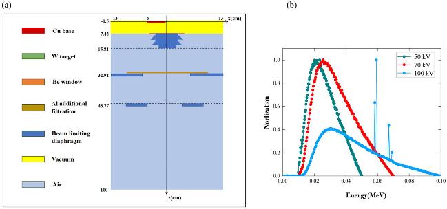
Figure 1(a) shows the simulation model of the X-ray machine established using the BEAMnrc program, including the target material, additional filtration, diaphragm, and other parameter settings. Figure 1(b) shows the fluence spectra of three superficial X-ray radiotherapy radiation qualities simulated at 50, 70, and 100 kV. Based on the established X-ray tube model, we selected the density correction database, chose whether to open the relevant particle reactions, and obtained a phase-space file. The phase-space file was opened in the BEAMdp software program and set to generate 200 spectral energy datasets with a minimum particle energy of 0.001 MeV. According to the fluence spectra datasets, the mean energies of the fluence spectra simulated at 50, 70, and 100 kV were 26.2, 34.1, and 44.7 keV, respectively.
HVL Measurements
The half-value layer (HVL) can be used to characterize the X-ray radiation quality, which is divided into the first HVL (1st HVL) and the second HVL (2nd HVL) [39]. The 1st HVL is defined as the thickness of the absorber required when the air kerma rate is reduced to 0.5 times the air kerma rate value in the case in which no absorber is used; the 2nd HVL is defined as the absorber thickness required when the air kerma rate is reduced to 0.25. The homogeneity coefficient (h) is the ratio of the 1st and the 2nd HVLs. A model diagram of the experimental setup for measuring HVL is shown in Fig. 2.
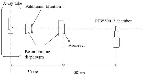
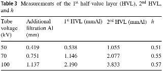
According to the measurement method for the HVL in [40], the Farmer chamber PTW30013 was used to measure the ionization current at a distance of 1 m from the focal spot of the X-ray tube, and the absorber was placed at a distance of 0.5 m. Based on the ionization current measured for different absorber thicknesses, the attenuation curve was fitted to estimate the 1st and 2nd HVLs. Figure 3 shows the attenuation curves of the three radiation qualities of superficial X-ray radiotherapy in the chamber PTW30013, where the vertical coordinates were normalized according to the maximum ionization current. Table 3 lists the measurements for the 1st and 2nd HVLs and h.
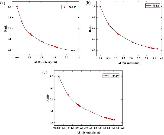
4: Measurements of the 1st half-value layer (HVL), 2nd HVL, and h
Absolute air karma measurements
According to the principle of FAC air kerma measurements, the chamber was fixed at a distance of 1 m from the focal spot of the X-ray tube using a laser and a measuring rod positioning device under established reference radiation quality conditions. The effective measurement center axis of the ionization chamber and the X-ray beam center axis were on the same horizontal line. The FAC was connected to a microcurrent measurement system, and the ionization current was measured using the high-gain negative feedback method. The air kerma rate was measured at a position 1 m from the X-ray focal spot using the FAC by measuring and simulating the relevant correction factors and combining them with the FAC.
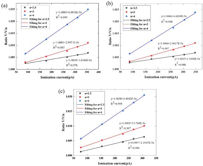
The ion recombination loss correction factor ks was measured at different tube voltages and currents. Five tube currents were set at each tube voltage for each radiation quality, and three tube voltages were simultaneously set at the same time to obtain 15 corresponding ionization currents. The ionization currents for the different tube currents at each tube voltage were processed with an ionization current at a polarizing voltage of +1600 V to obtain the ks fitting curves. The fitting curves of ks for three radiation qualities are shown in Fig. 4, and the values of kinit and kvol are listed in Table 4.
Calculated averages of initial recombination and volume recombination
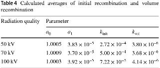
Table 4 lists the initial and volume recombination values for the three radiation qualities at different tube voltages. The values were calculated from the ionization current at different tube currents and voltages. The average initial and volume recombination values were calculated. According to Equation 7, the ks values at 50, 70, and 100 kV were 1.0009, 1.0011, and 1.0007, respectively.
 was introduced as a correction factor for air kerma for the first time in the ICRU Report 90. The value of
 of monoenergetic photons (energy range of 1–400 keV) is recommended, and
 of the radiation qualities in superficial X-ray radiotherapy cannot be obtained directly. In this study, fluence spectra datasets simulated by the EGSnrc software were used to calculate the products
 of the radiation qualities. Based on the
 values of the different monoenergetic photons, the original software program was used to interpolate the products
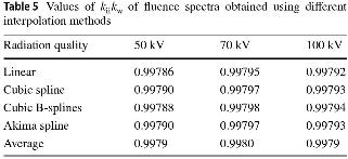
 at each energy level in the fluence spectra. Based on the simulated data, the product outcomes kiikw of the fluence spectra were calculated at the three radiation qualities using different interpolation methods, including linear, cubic spline, cubic B-spline, and Akima spline interpolation, as shown in Table 5; the final results were the average results.
Values of  of fluence spectra obtained using different interpolation methods
The correction factors for the superficial X-ray radiation qualities are summarized in Table 6, and the results for the air kerma rate are summarized in Table 7.
Correction factors of the three radiation qualities studied herein

Absolute air kerma measurements

Calibration of transfer ionization chambers
To verify the accuracy of the measured air kerma rate, the transfer chamber was calibrated, and the results were compared with international comparison results. The calibration factor is the ratio between the measured value corrected by the temperature and pressure using the transfer ionization chamber. The standard values were measured using the same reference radiation field. Equation (13), which is used to calculate the calibration factor, is given by (13)where
 is the standard air kerma rate, and Itr is the measured ionization current (corrected to 293.15 K and 101.325 kPa) by a transfer ionization chamber.
Considering the fluence of multiple electron scattering and recombination loss, the parallel-plate ionization chamber can reduce the fluence for the measurements of radiation quality at the low-energy X-ray superficial radiotherapy level because of its special structure. Two parallel-plate transfer chambers, namely PTW23342 (0.02 cm3) and PTW23344 (0.2 cm3), were used for the calibration. The effective measurement centers were the geometric centers of the front surfaces of the chambers. During the calibration of the transfer ionization chambers, the ionization current was measured using a connected microcurrent measurement system. It is necessary to focus on the changes in temperature and humidity in the measurement environment. Two transfer ionization chambers were placed in the radiation field, and the reference point of the transfer ionization chambers coincided with the measurement point of the air kerma measured using FAC to implement the subsequent calibration. The effective measurement volumes of the two transfer ionization chambers were low, particularly when the magnitude was approximately 1 pA when PTW23342 was used. When the external environment changes, such as the leakage current, the leakage current changes by 1 fA (ionization current is approximately 1 pA), which leads to an effect of 0.1%. It is necessary to measure the ionization current several times, estimate the average value to reduce uncertainty, and then obtain the calibration factor of the transfer chamber in superficial X-ray radiotherapy radiation qualities. The ionization current was measured under the same conditions as the five CCRI radiation qualities (10–50 kV) using two transfer chambers. In this study, FAC was used to measure the radiation quality of the CCRI air kerma rate (10–50 kV), and the  values were considered to obtain the calibration factors. The calibration factors of five CCRI radiation qualities (10–50 kV) and three radiation qualities in superficial X-ray radiotherapy are plotted in Fig. 5.
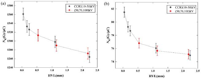
The black points in Fig. 5 correspond (from left to right) to 10 kV, 30 kV, 25 kV, 50 kVb, and 50 kVa for the CCRI series, and the red points correspond to 50, 70, and 100 kV for superficial X-ray radiotherapy. According to the measurements, the calibration factors changed for different radiation qualities as a function of X-ray energy. Figure 5 shows the calibration factor curves for the two transfer ionization chambers. There was a significant decrease when the X-ray energy was low, and it changed smoothly at increasing energies. This was consistent with the energy response of the ionization chamber design. Meanwhile, the calibration factors of the two transfer ionization chambers (namely PTW23342 and PTW23344) for the three radiation qualities in superficial X-ray radiotherapy were in good agreement with those of the CCRI radiation qualities. These results are traceable and equivalent to the international results for low-energy X-ray air. The accuracy of the measurement method for the air kerma rate of radiation qualities in superficial X-ray radiotherapy was verified indirectly.
Uncertainty analysis
The FAC measurements and transfer ionization chambers should consider the influence of uncertainty. The measurement uncertainty method was based on the GUM method. This includes uncertainties of Types A and B. The Type A uncertainty was derived from experimental deviations. The Type B uncertainty was evaluated using all the relevant information on the possible variability of the measured quantities [41]. According to the air kerma rate equation, the sources of uncertainty include the volume of the ionization chamber, ionization current, temperature, pressure, ionization current correction factors, and physical constants. For example, the ionization current was measured 10 times repeatedly, and the average value was estimated and used as the final value. The Type A uncertainty of the ionization current originates from the experimental deviation of the 10 measurements. After the analysis, the uncertainties of the associated correction factors measured for FAC are listed in Table 8, and the uncertainties of the air kerma values are listed in Table 9. The calibration factors measured for the transfer chambers are listed in Table 10.
Uncertainties of correction factors for air kerma rate using the FAC

Uncertainties of air kerma rate using the FAC

Uncertainties of calibration factors for transfer chambers

Table 9 shows the results when the FAC was used to measure the air kerma rate; uncertainties were obtained from the correction factors and mean ionization energy  . The combined relative uncertainty was 0.47%. Two transfer chambers (PTW23342 and PTW23344) were used for the calibration. Compared with PTW23344, the effective measurement volume of PTW23342 and the measured ionization current were smaller; therefore, the uncertainty of its ionization current was higher. Table 10 shows that the resulting uncertainties in the calibration factors are primarily derived from the air kerma rate and ionization current. The combined relative uncertainties of the calibration factors were 0.50% and 0.48%, respectively. The expanded uncertainties for the calibration factors of the two transfer chambers were 1.00% (k = 2) and 0.96% (k = 2).
Conclusion
In this study, the absolute measurements and uncertainty evaluations of air kerma under three radiation qualities in a superficial X-ray radiotherapy series were completed using an FAC. Two parallel-transfer ionization chambers were calibrated to obtain calibration factors and their uncertainties. Three radiation qualities were established based on the technical parameters of the SRT-100. The first HVLs measured were 0.538, 1.146, and 2.190 mmAl. A model of the FAC was constructed using the EGSnrc software program, and the particle fluence spectrum, mean energy, and corresponding correction factors of the fluence spectrum were simulated. Based on the experiments and simulations, correction factors of the air kerma rate were obtained, and the absolute measurements of the air kerma rate of the various radiation qualities were obtained in superficial X-ray radiotherapy. The air kerma rates were 1.487, 1.436, and 1.268 mGy/s with an expanded uncertainty of 0.94% (k = 2). Meanwhile, the radiation quality calibration of the two transfer ionization chambers was completed, and the expanded uncertainties of the calibration factors of the ionization chambers were 1.00% (k = 2) and 0.96% (k = 2). This research provides the basis for measurements of radiation qualities of the absorbed dose to water in superficial X-ray radiotherapy, greatly reducing measurement uncertainty and laying the foundation for the measurements of the absorbed dose.
References
1..
Xu F., Xiao X.L., Yu Q. et al., Patients’ subjective assessment and clinical effect analysis of 90Sr-90Y brachytherapy to keloids. Nuclear Techniques (in Chinese) 34(6), 460-464 (2011). https://cstr.cn/32193.14.j.issn.1674-3849.2011.6.460464. (in Chinese)
2..
Liu K., Wu X.L., Wang P.H., Advances in therapy of auricular keloid. Chin. J. Otorhinolaryngol Head Neck Surg. 51, 12 (2016). https://doi.org/10.3760/cma.j.issn.1673-0860.2016.12.015
3..
Mao S.R., Xiao Z.B., Treatment status and research progress of pathologic scars. Chin. J. Aesthetic Med. 31, 181–184 (2022). https://doi.org/10.15909/j.cnki.cn61-1347/r.004874
4..
Jia K.P., Zhou J., Research progress in the pathogenesis of keloids. J. Diagn. Ther. Dermato-Venereol. 30, 2 (2023). https://doi.org/10.3969/j.issn.1674-8468.2023.02.016 (in Chinese)
5..
Deng Q., Li X.F., Advances in the research on postoperative adjuvant radiotherapy for the treatment of keloids. J. Clin. Dermatol. 51, 10 (2022). https://doi.org/10.16761/j.cnki.1000-4963.2022.10.020
6..
Su W.X., Huang B., Zhang S.Y. et al., Research progress of brachytherapy in the treatment of keloid. Int. J. Radia. Med. Nucl. Med. 47, 9 (2023). https://doi.org/10.3760/cma.j.cn121381-202206011-00337
7..
Yan T.T., Hou J.J., Yan S.Y. et al., Efficacy analysis of surgical resection combined with electron beam irradiation in the treatment of keloids. J. Tissue Eng. Reconstr. Surg. 17, 4 (2021). https://doi.org/10.3969/j.issn.1673-0364.2021.04.007
8..
Meng L.J., Ma Y.Q., Wang L. et al., Preliminary exploration of the clinical effects of radiation therapy with SRT-100 on hypertrophic scars in children. Chin. J. Inj. Repair Wound Healing, Electron. Ed. 19, 16–23 (2024). https://doi.org/10.3877/cma.j.issn.1673-9450.2024.01.005
9..
Zhao D.L., Shi J.S., Li M.Z. et al., Clinical results of combination therapy for keloid patients. Chin. J. Clin. Med. 13, 690–691 (2006). https://doi.org/10.3969/j.issn.1008-6358.2006.04.076
10..
Elisa K.L., Richard F.C., Ernest S.C., Radiation therapy modalities for keloid management: a critical review. Br. J. Plast. Surg. 75, 8 (2022). https://doi.org/10.1016/j.bjps.2022.04.099
11..
Wang J.H., Yao H., Research progress in postoperative auxiliary radiotherapy of keloid. Med. Recap. 16, 2968–2970 (2015). https://doi.org/10.3969/j.issn.1006-2084.2015.16.031
12..
Wang W.J., Xie Y.X., Yang Y. et al., The application of surgical excision combining shallow X-ray radiation in the treatment of keloids. Tissue Eng. Reconstr. Surg. 12, 41–43 (2016). https://doi.org/10.3969/j.issn.1673-0364.2016.01.011
13..
Geng J.H., Shang X.F., Wang J.L. et al., Efficacy of surgical excision combined with superficial X-ray in the treatment of keloid. China J. Lepr. Skin Diseases. 32, 278–280 (2016). http://www.zgmfskin.com/CN/Y2016/V32/I5/278
14..
Deng Q., Li X.F., Advances in the research on postoperative adjuvant radiotherapy for thetreatment of keloids. J. Clin. Dermatol. 51, 10 (2022). https://doi.org/10.16761/j.cnki.1000-4963.2022.10.020
15..
You C.H., Sun T., Li J.J. et al., Core resection combined with superficial X-ray radiation for the treatment of ear keloids. Chin. J. Med. Aesth. Cosmet. 24, 3 (2018). https://doi.org/10.3760/cma.j.issn.1671-0290.2018.03.023
16..
Hong M., Zhang S.J., Yu D.J. et al., Research progress of postoperative radiotherapy in the treatment of keloid. Int. J. Radiat. Med. Nucl. Med. 45, 3 (2021). https://doi.org/10.3760/cma.j.cn121381-202007019-00029
17..
Ma C.M., Coffey C.W., DeWerd L.A. et al., Report No. 076-AAPM protocol for 40–300 kV x-ray beam dosimetry in radiotherapy and radiobiology. Med. Phys. 28, 6 (2001). https://doi.org/10.1118/1.1374247
18..
Klevenhagen S.C., Aukett R.J., Harrison R.M. et al., The IPEMB code of practice for the determination of absorbed dose for x-rays below 300 kV generating potential (0.035 mm Al-4 mm Cu HVL; 10-300 kV generating potential). Phys. Med. Biol. 41, 12 (1996). https://doi.org/10.1088/0031-9155/41/12/002
19..
International Atomic Energy Agency, Absorbed Dose Determination in External Beam Radiotherapy. Technical Reports Series No. 398, IAEA, Vienna, 2000. https://www.iaea.org/publications/5954/absorbed-dose-determination-in-external-beam-radiotherapy
20..
Lu P.Z, Wu J.J., Li M.Y. et al., Study on scatter radiation of low energy X-ray absorbed dose to water measurement. Nuclear Techniques (in Chinese) 45, 040202 (2022). https://doi.org/10.11889/j.0253-3219.2022.hjs.45.040202
21..
Ge S., Wu JJ., Guo B. et al., The establishment of reference radiation device in the range of (20-300) kV X-rays. Nucl. Electron. Detect. Technol. (in Chinese) 36, 68–72 (2016). https://doi.org/10.3969/j.issn.0258-0934.2016.01.017
22..
Wu J.J., Yang Y.D., Wang P.W. et al., Design and preliminary test of a free-air ionization chamber for low-energy X-ray. Chinese Phys. C 35, 576 (2011). https://doi.org/10.1088/1674-1137/35/6/013
23..
Zhao R., Wu J.J., Fan S. et al., Key comparison of the air-kerma of the NlM and the BlPM in low-energy X-rays. Acta Metrologica Sinica 43, 1359–1365 (2022). http://jlxb.china-csm.org:81/Jwk_jlxb/EN/10.3969/j.issn.1000-1158.2022.10.17
24..
Kawrakow I., Accurate condensed history Monte Carlo simulation of electron transport. Med. Phys. 27, 485–498 (2000). https://doi.org/10.1118/1.598917
25..
Fu J., Meng H.P., Ai K.W. et al., Cone beam CT simulation research based on EGSnrc software. Chin. Med. Equip. J. 40, 10 (2019). https://doi.org/10.19745/j.1003-8868.2019242
26..
Burns D.T., New correction factors for the BIPM free-air chamber standards. 2021, CCRI(I)/03-28. https://www.bipm.org/documents/20126/48195580/working-documentID-855/3c93966d-06f6-03e7-5e0a-2c9eb589c2c7
27..
Burns D.T., Kessler C., Wu J.J. et al., Key comparison BIPM.RI(I)-K2 of the air-kerma standards of the NIM, China, and the BIPM in low-energy x-rays. Metrologia. 56, 06006 (2019). https://doi.org/10.1088/0026-1394/56/1A/06006
28..
Zhao R., Wu J.J., Wen Y.Q. et al., Calibration method and absolute measurements of air kerma of diagnostic x-ray reference qualities using a free-air ionization chamber. Radiat. Prot. Dosim. 197, 28–35 (2021). https://doi.org/10.1093/rpd/ncab161
29..
Yu J.L., Wu J.J., Fang F. et al., Study on air attenuation correction factor of low energy free air ionization chamber, in the 18th National Academic Annual Conference of Nuclear Sub-science and Nuclear Detection Technology (2016). https://xueshu.baidu.com/usercenter/paper/show?paperid=1y750e400a7d0mp0kp4b06e0nm043182
30..
Derikum K., Correcting for ion recombination effects in ionization chambers consistently in continuous and pulsed radiation, in IAEA, International symposium on standards and codes of practice in medical radiation dosimetry Conference (2003). https://www.researchgate.net/publication/237455806_Correcting_for_ion_recombination_effects_in_ionization_chambers_consistently_in_continuous_and_pulsed_radiation
31..
Picard S., Burns D.T., Determination of the recombination correction for the BIPM parallel-plate ionization chamber type in a pulsed photon beam. (2011). https://www.bipm.org/en/scientific-output/ionizing-radiation/rapports-bipm
32..
Rogers D.W.O., Bielajew A.F., Wall attenuation and scatter corrections for ion chambers: measurements versus calculations. Phys. Med. Biol. 35, 1065 (1990). https://doi.org/10.1088/0031-9155/35/8/003
33..
Wang J., Study on measurement method of the air karma of W target-molybdenum filter X-rays. Dissertation, Hebei University of Science and Technology (2019)
34..
Ritz V.H., Design of free-air ionization chambers for the soft x-ray region (20–100 kV). Radiology 73, 911 (1959). https://doi.org/10.1148/73.6.911
35..
ICRU Report No. 90, Key data for ionizing radiation dosimetry: measurement standards and applications. J. Int. Commiss. Rad. Units Measur. 14, 3 (2014). https://doi.org/10.1093/jicru/ndw029
36..
Yu J.L., Wang P.W., Wu J.J. et al., Synchrotron radiation X-ray free-air ionization chamber electron loss and scattering fluorescence correction factor. Nucl. Electron. Detect. Technol. (in Chinese) 35, 12 (2015). https://doi.org/10.3969/j.issn.0258-0934.2015.12.002
37..
Li L., Wu J.J., Wang K., Correction factor of scattered photons and fluorescence photons for low-energy X-ray free-air ionization chamber research. Nucl. Electron. Detect. Technol. (in Chinese) 35, 12 (2015). https://doi.org/10.3969/j.issn.0258-0934.2015.02.003
38..
Burns D.T., Kessler C., Roger P. et al., Key comparison BIPM.RI(I)-K2 of the air-kerma standards of the ARPANSA, Australia, and the BIPM in low-energy X-rays. Metrologia 59, 06022 (2022). https://doi.org/10.1088/0026-1394/59/1A/06022
39..
Marashdeh W.M., Saleh H., Mass attenuation coefficient of olive peat material for absorbing gamma ray energy. Nucl. Sci. Tech. 30, 7 (2019). https://doi.org/10.1007/s41365-019-0637-8
40..
ISO 4037-1:2019, X and gamma reference radiation for calibrating dosemeters and doserate meters and for determining their response as a function of photon energy Part 1: Radiation characteristics and production methods. The State Bureau of Quality and Technical Supervision. https://www.iso.org/standard/66872.html
41..
Lee J.H., Lew K., Ludwing B. et al., The performance of the INER improved free-air ionization chamber in the comparison of air kerma calibration coefficients for medium-energy X-rays. Radiat. Measur. 39, 1–10 (2005). https://doi.org/10.1016/j.radmeas.2004.03.033